
Traditional data centers use a three-tier architecture to divide servers into different PODs based on physical location. This architecture consists of a core switch, an aggregation switch, and an access switch. Run the Spanning Tree Protocol (STP) between the aggregation switch and the access switch to ensure that the Layer 2 (L2) of the network has no loop. In the three-tier architecture, the servers in each POD belong to the same VLAN, so the server can migrate anywhere within the POD without modifying the IP address and gateway. The POD runs through the Layer 2 broadcast, and the POD takes three layers of routes. Therefore, the horizontal traffic path will be long (access→aggregation→core→aggregation→access), resulting in high latency. STP has many benefits: simple, plug-and-play (P&P), with very little configuration. However, STP cannot use the Parallel Forwarding Path, so it will always disable redundant paths within the VLAN, which means that 50% of the maximum link bandwidth will be blocked if there is no failure.
In 2010, Cisco introduced vPC (Virtual Link Channel) technology to address STP limitations. The vPC frees up ports that are disabled by STP, providing an Active-Active uplink between the access switch and the aggregation switch, leveraging the available bandwidth. When using vPC technology, STP acts as a Fail-safe Mechanism. The development of technologies such as virtual machines and containers has made the deployment of applications more and more distributed, resulting in a significant increase in the East-West-Traffic of the data center. These flows need to be processed efficiently, while still ensuring low, predictable delays. However, vPCs can only provide two parallel uplinks, so bandwidth in a three-tier data center architecture becomes a bottleneck.
With the development of virtualization technology, the POD-based two-layer design in the data center of the original three-layer network architecture can not meet the large-scale two-layer expansion requirements of virtualization and cloud computing. For example, Live Migration technology requirements such as vMotion require L2. The bigger the better. Therefore, the isolated computing, network, and storage resources in the POD form at the second layer should now be pooled (Pooled, which in turn spawns the Larger L2 Domain from the access layer to the core layer. The Layer 2 domain, the entire data center network, is an L2 broadcast domain (L2 Segment is extended to all PODs) so that data center administrators can create a centralized, more flexible, resource pool that can be allocated on demand. The server/virtual machine can be created and migrated anywhere, without the need to modify the IP address or default gateway.
The disadvantage of a large Layer 2 network is that BUM (Broadcase, Unknown Unicast, Multicast) will spread throughout the data center, which ultimately limits the size of the network. Because the network scale is large enough, the BUM storm will seriously affect normal network communication. This is another new topic proposed by network service providers in the development of data center networks, and the answer sheet delivered by service providers is the Overlay network.
Overlay network
Networks in modern virtualized data centers must meet specific preconditions in order to accelerate application deployment and support DevOps. For example, you need to support extended forwarding tables, extended network segments, L2 Segment Extension, virtual device drift (Mobility), forwarding path optimization, network virtualization on shared physical infrastructure, and multi-tenancy. The Overlay network can solve the above-mentioned problems, so manufacturers have introduced a variety of new Encapsulation Frame Formats this year:
- VXLAN
- GRE
- Geneva
- NVGRE : Network Virtualization Using Generic Routing Encapsulation
- TRILL : Transparent Interconnection of Lots of Links
- LISP : Location/Identifier Separation Protocol
The Overlay network refers to a virtual network built on the basis of the existing network (Underlay Network). The so-called Underlay network is the network where the previous switch is located, as long as it is an IP network. The newly built Overlay network is used as a network for server communication. The Overlay network is an L3 in L2 network. In other words, as long as the L3 network can cover, the Overlay L2 network can also be covered.
In short, the Overlay network is a virtual network formed by interconnecting nodes of the underlying network (Underlay Network), which enables applications with specific requirements for the network topology to be deployed without modifying the underlying network.
The advantages of the Overlay network
Optimized device capabilities: The Overlay network allows devices to be categorized (and customized) based on their location in the network. An Edge or Leaf device can optimize its functionality and associated protocols based on terminal status information and size; Core or Spine devices can optimize its functionality and protocols based on link-state and optimize for fast convergence.
Fabric scalability and flexibility: The Overlay network enables network expansion on Overlay edge devices. When using Overlay on a fabric boundary, the Spine or Core device does not need to add end-host information to its forwarding table (eg if the Overlay is encapsulated and decapsulated in the host, the Overlay boundary is inside the host).
Overlapping IP Addresses: Most Overlay technologies used in data centers support virtual network IDs (VIDs) to uniquely scope and identify each private network. This limitation allows the MAC and IP addresses of different tenants to be overlapped. The overlay’s encapsulation separates the management of the tenant address space from the underlay address space.
Spine-Leaf network architecture based on VxLAN Overlay
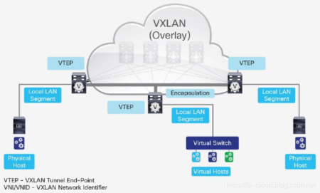 The VxLAN-based Overlay network builds a layer of L2 Overlay network on top of the L3 IP Underlay network to transport L2 packets through the VTEP tunneling mechanism. For example, in the following figure, the original switch network is unchanged, and the server implements the L2 network across the Leaf switch through the Overlay network. In this way, in an Overlay network, the server can be deployed arbitrarily, regardless of the architecture of the existing network.
Spine-Leaf based on VxLAN Overlay
A complete, VxLAN Overlay-based Spine-Leaf network architecture is shown below. This network architecture is called VxLAN Fabric and is usually implemented in two ways: one is based on the Flood-Learn mode, similar to the traditional L2 network; the other is based on MP-BGP EVPN as the control layer. The VM in the architecture does not know the existence of the VxLAN Overlay, and the VM just sends the Ethernet Frame. After the VTEP (VxLAN Overlay on the Leaf switch needs to be integrated with the VTEP on the Leaf switch) receives the Ethernet frame of the VM, it is automatically encapsulated into a VxLAN packet (essentially a UDP packet) and then in the original Spine. L3 transmission on -Leaf’s Underlay network. The Spine-Leaf network architecture based on VxLAN Overlay breaks the limitation of the large Layer 2 network in this way, limiting the L2 broadcast domain to the Underlay (Leaf node) and extending the POD to the entire Overlay.
Original Article Source from https://blog.csdn.net/Jmilk/article/details/98220139